






jasonhardware@foxmail.com+86-0574-58202256
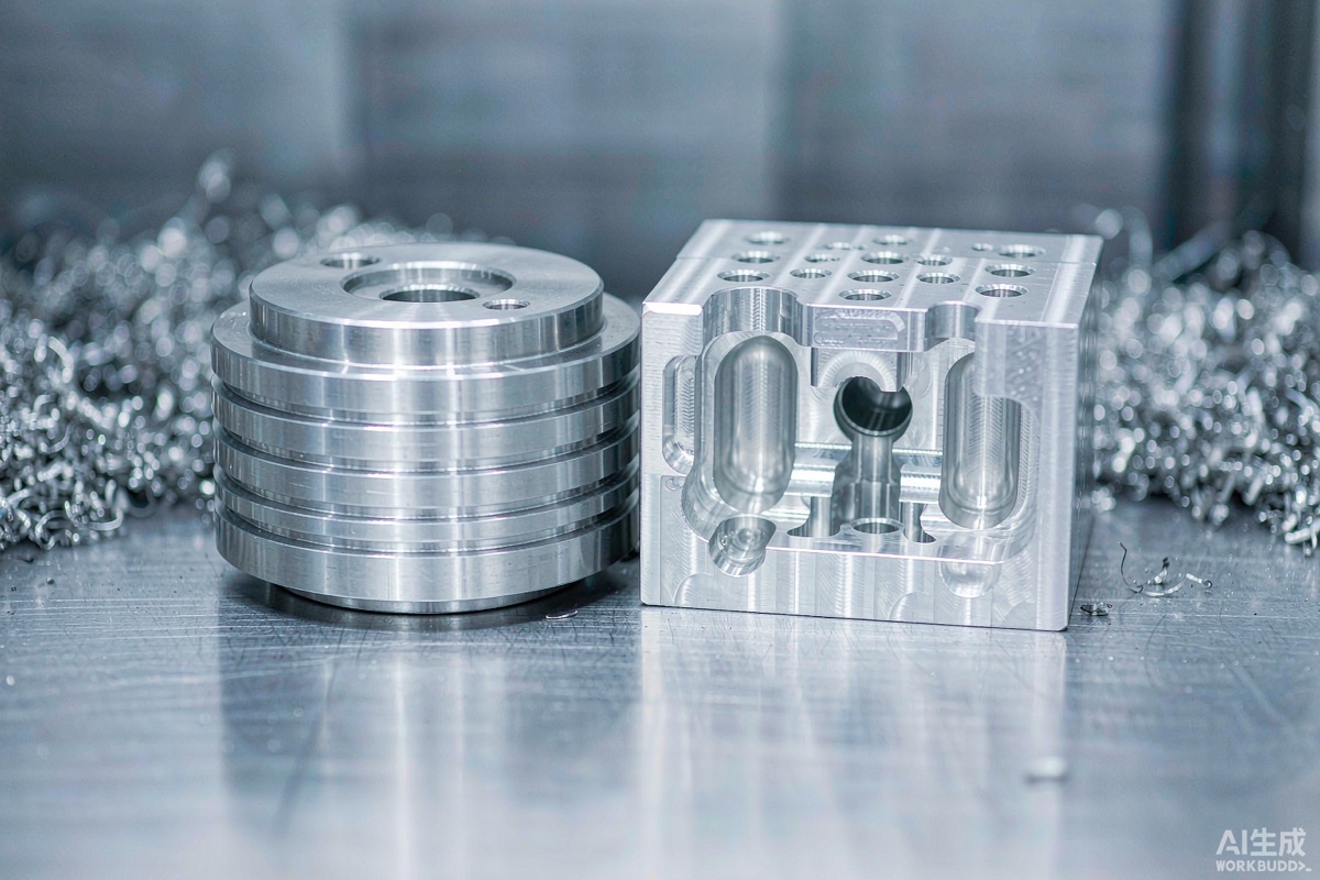
Every week a customer sends us a drawing and asks the same question: turning or milling? The honest answer is that the part usually decides, not the buyer. But understanding the difference helps you design cheaper parts and read quotations more intelligently.
This guide from Ningbo Renjiu Machinery explains both processes, compares them feature by feature, and gives a simple decision rule you can apply to your own drawing.
In turning, the workpiece rotates and a stationary cutting tool feeds into it. The machine is a lathe — in a modern shop, a CNC lathe or a turn-mill centre. The material is usually supplied as round bar.
Turning is the natural process for axisymmetric parts: anything that is fundamentally cylindrical. Typical output:
The characteristic turned feature is the outside diameter and the face — produced with continuous, single-point cutting that is fast and repeatable. Threads, grooves and chamfers are all natural turning operations.
In milling, the tool rotates and the workpiece stays still (or moves in a controlled way). The machine is a milling machine — usually a vertical or horizontal machining centre, sometimes with 4 or 5 axes of motion.
Milling produces prismatic parts: anything built around flat faces, pockets and holes. Typical output:
The characteristic milled features are pockets, slots, profiles and hole patterns. Multi-axis milling can also generate complex 3D surfaces such as impellers, mould cores and sculpted covers.
| Factor | CNC Turning | CNC Milling |
|---|---|---|
| Motion | Part rotates, tool is stationary | Tool rotates, part generally stationary |
| Ideal geometry | Round, axisymmetric, threaded | Prismatic, pockets, holes, profiles |
| Starting material | Round bar, tube, castings | Plate, block, castings |
| Typical tolerance | ±0.02 mm routine, ±0.005 mm precision | ±0.05 mm routine, ±0.01 mm precision |
| Surface finish | Often better out of the cut on cylindrical faces | Depends heavily on tool reach and rigidity |
| Setup count | Low — most features from one orientation | Can be high on multi-face parts |
| Best for volume | Excellent — bar feeders run unattended | Good, especially with pallets and multi-vice setups |
| Cost driver | Bar diameter, length-to-diameter ratio, thread count | Pocket depth, corner radii, number of setups |
Ask one question: if I spin this part about its main axis, does the shape stay the same?
This rule works because the geometry of the machine determines which features are cheap. Fighting it by, say, milling a long thin shaft out of a plate is technically possible and economically painful.
Modern multitasking machines combine a lathe spindle with live tooling, a secondary spindle and sometimes a B-axis. A single bar-fed cycle can turn the profile, mill the flats, drill the cross holes, tap the threads and part off the component.
Where turn-mill wins decisively:
Where it does not: large prismatic parts, and very simple parts where a dedicated lathe or mill is simply faster.
For tolerance guidance in numeric terms, see CNC machining aluminium tolerances explained. For material behaviour, our metal materials page covers the common alloys and their machinability.
Yes. Hex bar stock is turned directly, and square or hexagonal flats on round parts are milled on a turn-mill machine. It does not change the underlying process.
Not inherently. Turning holds roundness and concentricity more easily because the part rotates on a single axis, but a well-set-up milling machine with a rigid fixture holds tight tolerances too. Process capability depends on the machine, tool and setup — not on the process name.
Whichever matches the geometry. For a cylindrical part, turning is dramatically cheaper. For a bracket, milling instantly wins. Asking for the wrong process is the most expensive decision on the drawing.
Yes — we machine both. Send your drawing and our engineers will tell you which process gives the best combination of price, tolerance and lead time, rather than simply quoting what you asked for.
Not sure which process your part needs? Send the drawing to our engineering team — we will recommend the most cost-effective route before quoting.
Send your 2D/3D files and get a detailed quotation within 24 hours — DFM feedback, material and tolerance advice, and lead time included. Prototypes from 1 piece, no minimum order.
Request a Free Quote → WhatsApp Us
Or email jasonhardware@foxmail.com · Reply within 24 hours, Monday–Saturday
Contact: Mr Zhang
Phone: +86-18368240367
E-mail: jasonhardware@foxmail.com
Add: No.16 Laoshan Road, Beilun District, Ningbo City
LiveChatclose
 Send Email
 WhatsApp