






jasonhardware@foxmail.com+86-0574-58202256
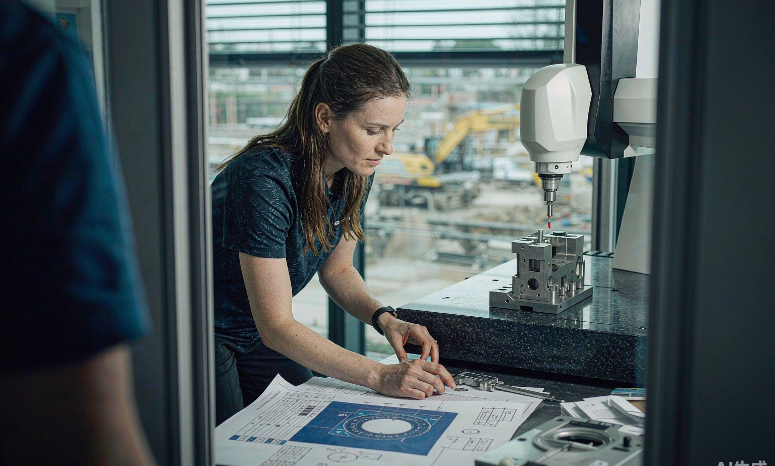
Most quoting friction between a buyer and a machine shop traces back to the drawing — not to the price list. Symbols from Geometric Dimensioning and Tolerancing (GD&T) carry enormous information in tiny frames, and when they are applied without intent they quietly add cost: every over-tight datum or profile callout is inspected, and inspection is labour. This guide explains the GD&T symbols that actually appear on CNC machining drawings, what each one costs you, and how to annotate a drawing so it manufactures efficiently.
Plain plus/minus tolerances answer "how big?", but real parts fail on geometric relationships — a bore that is perfectly sized but tilted, a face that is flat everywhere but tilted 0.5° to the bore axis. GD&T solves this with a datum system: you declare which surfaces the part functions from (datums A, B, C), then tolerance every feature's relationship to them. A well-datumed drawing lets the machinist and inspector set up the part the same way it will function in the assembly — which is also why it can save money: functional tolerancing is usually looser than blanket ±0.01 everywhere.
| Symbol / Control | Controls | Typical machined use | Cost note |
|---|---|---|---|
| Flatness ⏥ | Surface plane, no datum | Gasket faces, mounting pads | Sub-0.05 mm needs grinding or fly-cutting — specify only on sealing faces |
| Perpendicularity ⊥ | Surface/axis to datum, 90° | Bores to faces, bosses to base | Usually achieved free in one setup; tight values force second ops |
| Position ⌖ | Axis location to datums | Hole patterns, dowel holes | The workhorse — replaces coordinate ± dimensions on patterns |
| Profile of a surface ⌓ | True 3D contour to datums | Cosmetic and mating contours | Tight profiles need 5-axis finishing and scanning inspection |
| Concentricity ◎ | Median points to datum axis | Rarely justified | Expensive to inspect; use runout or position instead |
| Circular runout ↗ | Surface rotation around datum | Shafts, spinning parts | Cheap to check on centres or a V-block — preferred over concentricity |
| Surface texture | Ra / Rz roughness | Sealing and sliding faces | See our Ra guide below; each halving of Ra multiplies finishing cost |
A machined part fixes itself in space the way a surface plate does: primary datum (three points of contact — usually the largest face), secondary datum (two points — a long edge or dowel axis), tertiary datum (one point — a stop). Match your datum references to how the part actually mounts in the assembly, and machining becomes predictable: we clamp on the datums, cut everything in one setup, and measurement mirrors assembly.
Two practical mistakes we see weekly:
Hole patterns toleranced with ±0.05 in X and Y create a square zone, and diagonal holes actually get ±0.07 of freedom while straight-axis holes get ±0.05 — inconsistent by construction. GD&T position with a diameter zone (⌖ | ⌀0.1 | A | B | C) fixes that: the tolerance zone is a cylinder 0.1 across, matching how a fastener actually fits. Bonus: with a position callout the feature can be inspected with a functional gauge, which is faster and cheaper than CMM probing every hole's XY independently. The exception to watch: MMC modifiers (Ⓜ) buy tolerance as features depart from size — great for clearance holes, never appropriate for press-fit dowels.
Symbols don't set cost — the numbers inside the frames do. Two anchors from our CNC tolerance guide: standard 3-axis milling holds ±0.05–0.1 mm without discussion, and ±0.01 mm is production-realistic on critical features only. The same ratio applies geometrically — perpendicularity within 0.02 mm on a long bore, or flatness 0.01 mm on a 200 mm face, each drag in grinding, lapping or stress relief. Our rule: tolerance what the function needs, default the rest to the shop standard (we print ours on every quote).
Every quote begins with a drawing review: we check datum feasibility, stack up the geometric callouts against the process, and reply with questions before quoting rather than deviation requests after production. Complex prismatic parts with tight profile callouts go to our 5-axis cells; rotating geometry with runout controls goes to turning with in-process gauging. Inspection reports include CMM data on every GD&T frame, per the workflow in our quality control guide.
Not everywhere. Simple parts with one or two critical features work fine with dimension-plus-flatness callouts. GD&T pays off when multiple features must relate to each other — patterns, fits, sealing — or when you need functional gauging in production.
Plan on ±0.1 mm general, ±0.05 mm comfortable, ±0.02 mm achievable on short features, and treat ±0.01 mm as a spec you pay for. Geometric frames follow the same ladder.
Concentricity controls median points — it requires measuring diametrically opposed points and is slow even on a CMM. Runout or position controls nearly always express the same design intent at a fraction of the inspection cost.
Yes — send the CAD model and duty description, and our engineers will propose datums and geometric callouts based on how the part functions, then quote to that drawing.
Have a drawing you suspect is over-toleranced? Email it to sales@nbrjmetal.com — we will mark up the GD&T for manufacturability and show you what each frame adds to the price.
Send your 2D/3D files and get a detailed quotation within 24 hours — DFM feedback, material and tolerance advice, and lead time included. Prototypes from 1 piece, no minimum order.
Request a Free Quote → WhatsApp Us
Or email jasonhardware@foxmail.com · Reply within 24 hours, Monday–Saturday
Contact: Mr Zhang
Phone: +86-18368240367
E-mail: jasonhardware@foxmail.com
Add: No.16 Laoshan Road, Beilun District, Ningbo City
LiveChatclose
 Send Email
 WhatsApp