






jasonhardware@foxmail.com+86-0574-58202256
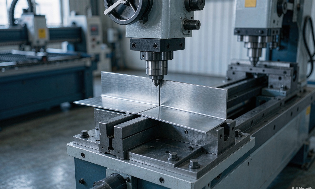
Sheet metal is the fastest route from a flat pattern to a finished bracket, enclosure or chassis — but it is also the process where small design decisions move cost the most. A bend radius that fights the tooling, a hole placed too close to a bend, or a thickness that changes between flanges can turn a straightforward job into rework. This guide collects the rules we apply every day on the press brake and the fibre laser, so your next sheet metal fabrication project quotes faster and builds cleaner.
The first cost lever in sheet metal fabrication is thickness. Every extra gauge on a drawing means another material stock, another setup on the laser, and often another quotation line. Design the whole part around one thickness wherever you can — 1.0, 1.5, 2.0 and 3.0 mm cover the vast majority of brackets and enclosures we build.
Two habits help here:
Sheet metal bending is a plastic-forming operation, so the inside bend radius cannot be chosen freely. The reliable rule is inside radius = 1× material thickness for steel and aluminium up to about 3 mm. Sharper inside radii stretch the outer fibre and crack anodised or powder-coated surfaces; much larger radii need special tooling and make flange lengths harder to hold.
Because the neutral axis shifts during bending, flat-pattern development uses the K factor — typically 0.33–0.5 depending on material and radius. You do not need to calculate it yourself: send the 3D model, and the fabricator's CAM will unfold it with the correct bend allowance for their tooling. What you should control is consistency — keep the same inside radius on every bend of a part, and tooling changes during production disappear.
Guides for laser cutting sheet metal agree on one thing: geometry near a bend is where designs break. Follow three minimums and most problems vanish:
Slots should end in full radii, and rectangular cutouts near a flange should get a bend relief — a small cut that isolates the deformed zone so the flange can form cleanly without tearing the corner.
Blank dimensions cut on a fibre laser hold ±0.1 mm comfortably, and hole positions hold ±0.1 mm to a datum. Bends are different: angular tolerance of ±1° and flange length of ±0.2 mm are realistic production targets, with springback compensated per material lot. Stacking three flanges in one assembly can accumulate those angles, so tolerance the assembly gap, not each flange to aviation decimals. Our separate guide covers tolerance strategy for machined parts, and the same philosophy applies: specify what the function needs, not what the CAD software defaults to.
Finish choice on sheet metal is as much about process order as appearance. Powder coating happens after forming and cures at temperature, which is economical on large enclosures. Anodising on aluminium happens after fabrication too, and gives a harder, thinner film with good electrical behaviour — we compared the two routes in detail in Anodizing vs Powder Coating. Two sheet-specific warnings:
Quoting for sheet metal fabrication follows a different logic from machining. Machine time is cheap; the expensive lines are material utilisation and setups. Four factors dominate:
| Factor | Why it moves price | Design response |
|---|---|---|
| Nesting efficiency | Parts that tile tightly waste less sheet | Use standard blank sizes; share one flat pattern across variants |
| Number of bends | Every bend is a handling and setup step | Merge flanges; accept 2 bends instead of 4 when stiffness allows |
| Special tooling | Gooseneck or hemming tools cost setup time | Standard radii and depths reuse the press brake's daily toolkit |
| Hardware insertion | Pemb/standoff placement is per-piece labour | Group insertions on one face; keep them off tight flanges |
If your volumes are climbing past a few hundred units and walls are getting thicker, it can be cheaper to switch technology entirely — castings or mouldings sometimes win at scale. We walk through that decision in 3D Printing vs CNC Machining and in our machined-part cost breakdown.
Sheet metal is unusually friendly to iteration because the tooling is generic: the same press brake that bends ten prototypes bends ten thousand. A sensible progression is laser-cut blanks for the first fit-check, a fully formed prototype with hardware and finish for approval, then batch production against the same flat pattern. Renjiu runs this workflow daily — you can see the process on our sheet metal fabrication service page, browse typical sheet metal parts, or check grade options on the sheet metal materials guide.
0.5 mm aluminium and 0.8 mm mild steel bend repeatably on standard tooling. Below that, parts tend to oil-can and handling damage rises — consider chemical etching or stamping instead.
Yes — that is the normal sequence (cut → punch → bend → weld → finish). Features placed too close to bends are the one thing the sequence cannot rescue, so apply the 2.5× rule before sending the drawing.
Tooling marks come from the die radius. For visible faces we use polyurethane-pad bending or specify the grain side away from the bend, then deburr and finish over the tool marks.
On request. Sending a STEP model is enough for us to unfold with the correct K factor; a DXF of your own flat pattern speeds quoting but we always re-verify against the 3D model.
Have a bracket or enclosure drawing ready? Send the STEP or DXF to sales@nbrjmetal.com — we will return a firm lead time, a flat-pattern check and unit pricing within one working day.
Send your 2D/3D files and get a detailed quotation within 24 hours — DFM feedback, material and tolerance advice, and lead time included. Prototypes from 1 piece, no minimum order.
Request a Free Quote → WhatsApp Us
Or email jasonhardware@foxmail.com · Reply within 24 hours, Monday–Saturday
Contact: Mr Zhang
Phone: +86-18368240367
E-mail: jasonhardware@foxmail.com
Add: No.16 Laoshan Road, Beilun District, Ningbo City
LiveChatclose
 Send Email
 WhatsApp